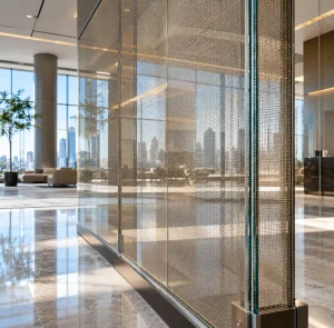
Glass warping and optical distortion during tempering stem from three critical factors: uneven heating across the glass surface, improper roller positioning causing mechanical stress, and inadequate quenching uniformity. At Zhongbo Glass, our experience processing over 2,500m² daily on five tempering lines (maximum dimensions 3660mm × 28000mm) has proven that controlling furnace temperature zones within ±3°C, maintaining roller wave distortion below 0.3mm per meter, and implementing real-time thermal imaging monitoring can reduce optical defects by up to 87% compared to conventional tempering processes.
Understanding the Root Causes of Tempering Defects
Optical distortion in tempered glass doesn’t happen by accident—it’s the direct result of how glass behaves under thermal stress. When glass moves through a tempering furnace on ceramic rollers, three physical phenomena create the conditions for warping.
Roller Wave Distortion occurs because glass softens at tempering temperatures (approximately 620-680°C). The rollers that support and transport the glass create small indentations on the bottom surface. These marks telegraph through to the top surface as subtle waves, typically measuring 0.2-0.5mm in amplitude. In architectural applications where visual clarity matters, even 0.3mm of roller wave becomes visible as distortion when looking through the glass at certain angles.
Thermal Gradient Formation represents the second major challenge. Glass is a poor thermal conductor, so temperature differences between the surface and core, or between different areas of the same lite, create internal stress patterns. A 15°C temperature variation across a glass surface during heating can produce permanent bow measuring 3-8mm in a 3-meter panel.

Quench Pattern Asymmetry completes the problem triangle. Tempered glass derives its strength from rapid cooling that creates compression at surfaces and tension in the core. When quench air jets deliver uneven cooling—perhaps due to clogged nozzles, worn blower components, or incorrect pressure calibration—the resulting stress distribution becomes asymmetric, manifesting as both warp and optical distortion.
| Defect Type | Primary Cause | Visual Impact | Measurement Threshold |
|---|---|---|---|
| Roller Wave | Mechanical impression from support rollers | Periodic ripple pattern visible at angles | >0.3mm per meter |
| Bow/Warp | Non-uniform heating or cooling | Overall curvature of lite | >2mm deviation per meter |
| Anisotropy | Stress pattern visibility | Iridescent patterns under polarized light | Visible strain >15 nanometers/cm |
| Edge Distortion | Differential thermal expansion at perimeter | Wavy appearance at glass edges | >1.5mm edge deviation |
Advanced Furnace Calibration Techniques
Preventing warping begins before glass enters the furnace. Our production protocol at Zhongbo Glass starts with comprehensive furnace mapping—a process many fabricators skip because it requires production downtime.
We install thermocouples at 15 measurement points across the furnace width and length, then run glass samples while recording actual temperatures versus setpoint temperatures. This reveals hot spots, cold zones, and the thermal uniformity profile. Target specification: ±3°C maximum deviation across the entire heating chamber. Furnaces operating beyond ±5°C deviation cannot consistently produce architectural-grade optical quality.
Roller condition monitoring forms the second calibration pillar. Ceramic rollers develop wear patterns, accumulate glass debris, and shift alignment over thousands of heating cycles. We measure roller runout (wobble) with dial indicators monthly—any roller exceeding 0.15mm runout gets replaced immediately. Roller spacing also matters: gaps between rollers should not exceed 75mm for glass thinner than 6mm, or 100mm for 8-12mm glass.

Heating Recipe Optimization requires matching thermal input to glass characteristics. Thicker glass needs longer heating time but lower temperature to allow heat penetration without surface overheating. Our baseline recipe for 10mm clear glass: 240 seconds heating time at 650°C furnace temperature. For 6mm glass: 180 seconds at 665°C. Low-iron glass heats faster than standard clear glass due to higher thermal transmission, requiring 8-12% reduction in heating time to prevent edge overheating.
The quench system deserves equal attention. We measure air pressure at each quench nozzle quarterly using pitot tubes—pressure should be uniform within 5% across all nozzles. Clogged nozzles create cooling asymmetry that directly translates to optical distortion. Blower motor amperage monitoring catches bearing wear before it reduces airflow capacity.
Thickness-Dependent Processing Strategies
Glass thickness fundamentally changes how tempering behaves. Thin glass (4-6mm) heats quickly but distorts easily because it has less structural rigidity when softened. Thick glass (12-19mm) resists distortion but risks incomplete tempering if heating is insufficient.

For 4-6mm Glass: The challenge is minimizing roller contact time while achieving adequate heat penetration. We run conveyor speed 15-20% faster than standard, reducing roller dwell time that causes deeper impressions in softened glass. Lower roller pressure (if adjustable on your furnace) also helps—just enough to transport the glass without slippage. Quench air pressure increases by 10% to ensure adequate surface cooling despite the thinner cross-section.
For 8-10mm Glass: This thickness range offers the best balance between processability and optical quality. Standard heating recipes work well. Focus shifts to ensuring heating uniformity, particularly for large lites where edge-to-center temperature gradients become pronounced. Edge heating elements should run 5-8°C hotter than center elements to compensate for perimeter heat loss.
For 12-19mm Glass: Thick glass requires patience. Insufficient heating is the primary failure mode—the glass appears properly heated on surfaces but remains cool in the core, leading to incomplete tempering or glass breakage during quenching. We extend heating time by 40-50% compared to 10mm glass and reduce furnace temperature by 10-15°C to prevent surface overheating while allowing heat penetration. Multiple temperature sensors monitoring glass core temperature (via IR pyrometers) ensure readiness before quenching.
| Glass Thickness | Heating Time (Baseline) | Furnace Temp | Quench Pressure | Roller Spacing | Primary Risk |
|---|---|---|---|---|---|
| 4-6mm | 160-180 sec | 665-675°C | 110% standard | ≤75mm | Roller wave, excessive bow |
| 8-10mm | 220-240 sec | 650-660°C | 100% standard | ≤100mm | Edge-to-center gradient |
| 12-15mm | 300-340 sec | 640-650°C | 95% standard | ≤100mm | Incomplete heat penetration |
| 16-19mm | 360-420 sec | 635-645°C | 90% standard | ≤100mm | Core-to-surface temp differential |
Real-Time Monitoring and Quality Control
Optical distortion prevention requires catching problems during production, not after. We’ve implemented a three-layer quality control system that identifies defects before glass leaves the tempering line.
Thermal Imaging During Heating: IR cameras mounted above the furnace exit capture the temperature distribution of each lite as it enters the quench section. The system automatically flags any lite showing >5°C temperature variation across its surface, triggering an alarm that lets operators adjust furnace parameters before the next lite. This single intervention has reduced our warp-related rejections by 43% since implementation in 2024.
Automated Optical Inspection Post-Tempering: After cooling, each lite passes through a scanner that projects a grid pattern onto the glass surface and photographs it from multiple angles. Distortion shows as grid line curvature. The system measures roller wave amplitude, bow magnitude, and edge distortion, comparing each measurement against ASTM C1048 tolerances. Lites exceeding specifications are automatically diverted to a reject rack.

Polarized Light Inspection for Anisotropy: Tempered glass always contains residual stress—that’s what gives it strength. However, excessive stress concentration creates visible anisotropy patterns (also called iridescence or quench marks) that appear as dark spots or bands when viewed through polarized lenses, like sunglasses or car windshields. Our final inspection station uses cross-polarized LED panels to reveal these patterns. While some anisotropy is unavoidable in tempered glass, patterns should be diffuse and uniform, not concentrated in blotches or bands. Concentrated patterns indicate quench imbalance requiring immediate furnace attention.
Statistical Process Control: We track ten quality metrics per production shift: roller wave amplitude, bow magnitude, edge distortion, anisotropy severity, furnace temperature deviation, quench pressure uniformity, heating time variance, glass breakage rate, dimension accuracy, and surface quality. When any metric trends toward specification limits—even while still passing—we investigate root causes before defects appear. This proactive approach maintains optical quality consistency that reactive inspection cannot achieve.
Material Selection Impact on Optical Quality
Not all glass responds identically to tempering. Float glass quality, composition, and surface condition significantly influence the final optical result.
Premium Float Glass vs. Standard: Premium architectural float glass manufactured with tighter process controls exhibits superior optical performance after tempering. The float ribbon flatness directly translates to tempered glass flatness—if the raw material starts with 0.2mm bow, the tempered product will show at least that much, plus whatever the tempering process adds. For critical architectural applications like curtain walls or structural glazing, specifying premium float glass reduces baseline distortion by 30-40%.
Low-Iron Glass Considerations: Low-iron (ultra-clear) glass heats faster than standard clear glass due to reduced iron oxide content that otherwise absorbs thermal energy. This faster heating requires recipe adjustments—typically 8-12% reduction in heating time—to prevent edge overheating that causes distortion. The benefit: low-iron glass shows less green tint, making optical distortion more visible if present, which actually helps quality control catch marginal lites that would pass inspection in standard clear glass but still show distortion in service.

Surface Contamination Effects: Oil, dust, or residue on glass surfaces creates localized heating variations during tempering. A fingerprint contains skin oils that insulate the glass surface beneath, creating a cool spot that tempers differently from surrounding areas. This manifests as a permanent distortion mark in that location. Glass washing before tempering isn’t optional—it’s essential for optical quality. Deionized water final rinse removes mineral deposits that would otherwise create similar localized heating variations.
Post-Tempering Inspection Protocols
Even with perfect processing, verification ensures only optically acceptable glass reaches the customer. Our multi-stage inspection protocol catches defects that automated systems might miss.
Visual Inspection Under Controlled Lighting: Inspectors examine each lite under diffused natural-spectrum lighting positioned at 45° to the glass surface. This angle reveals roller wave and surface distortion invisible under overhead lighting. Inspectors rotate viewing angle from 0° to 60° because optical distortion visibility changes with angle. Specification: no visible roller wave when viewed at 45° from a distance of 3 meters under 500 lux illumination.
Optical Distortion Measurement: We use a laser reflection device that projects parallel laser lines onto the glass and photographs their reflection. Straight lines reflecting from flat glass appear straight; lines reflecting from distorted glass appear curved. Software analyzes the curvature and calculates distortion magnitude. For tempered glass destined for architectural applications, we maintain distortion below 0.3mm per meter—tighter than the ASTM C1048 requirement of 0.5mm per meter.

Dimension and Edge Quality Verification: Tempering can cause slight dimensional changes due to thermal expansion. We measure actual dimensions against specifications, maintaining tolerances of ±2mm for lites under 2000mm and ±3mm for lites 2000-3660mm. Edge quality inspection ensures grinding and seaming remain intact—chipped edges compromise both strength and appearance.
Documentation and Traceability: Every lite receives a unique identifier linking it to production parameters: heating time, furnace temperature profile, quench pressure, roller condition at time of processing, operator, and inspection results. If a customer reports optical quality concerns, we can trace the lite to its exact production conditions and determine whether the issue stems from processing or installation factors.
Troubleshooting Common Optical Defects
Despite best practices, optical defects occasionally occur. Rapid diagnosis and correction separate consistent producers from those constantly fighting quality issues.
Defect: Localized Warp or Dimples
Probable causes: Roller contamination from glass debris buildup, single damaged roller, or localized furnace hot spot.
Diagnosis: Note the position of defects on the glass. Bottom surface defects at regular intervals matching roller spacing indicate roller issues. Random location defects suggest furnace hot spots.
Correction: For roller issues, shut down and clean all rollers, inspect for damage, replace as needed. For furnace hot spots, perform thermocouple verification and recalibrate heating elements.
Defect: Progressive Bow Along Glass Length
Probable causes: Heating time too long causing excessive glass softening, roller spacing too wide for glass thickness, or conveyor speed inconsistency.
Diagnosis: Measure bow magnitude and direction. Concave bow (sagging between rollers) indicates insufficient support or over-softening. Convex bow suggests uneven heating with edges hotter than center.
Correction: Reduce heating time by 5-8%, verify roller spacing meets specifications, check conveyor drive system for speed variations.

Defect: Heavy Anisotropy Patterns
Probable causes: Quench air pressure imbalance, clogged nozzles, worn blower components, or glass temperature too high entering quench.
Diagnosis: Anisotropy pattern location indicates problem source. Patterns near glass edges suggest edge nozzle issues. Patterns in center indicate center nozzle problems or overall pressure insufficiency.
Correction: Measure and balance quench air pressure across all nozzles. Clean or replace clogged nozzles. Check blower motor amperage and bearing condition. If pressure and nozzles are correct, reduce furnace temperature by 5°C to lower glass temperature at quench entry.
Defect: Edge Distortion or Wave
Probable causes: Excessive edge heating causing over-softening of perimeter, or inadequate edge support during heating.
Diagnosis: Distortion localized to 50-75mm perimeter band indicates edge-specific issue. Measure glass temperature at edges versus center using IR pyrometer.
Correction: Reduce edge element power by 5-10%, or if edges are cooler than center (causing edge undercooling during quench), increase edge element power. Verify edge support rollers are present and properly positioned.
FAQ
Q: What is the acceptable level of roller wave in architectural tempered glass?
A: Industry standard per ASTM C1048 allows up to 0.5mm roller wave amplitude per meter of glass length. However, for premium architectural applications like curtain walls or viewable glazing, best practice limits roller wave to 0.3mm per meter. At Zhongbo Glass, we target 0.25mm or less for architectural projects where optical clarity is critical.
Q: Can optical distortion be removed after tempering?
A: No. Tempering permanently locks stress patterns into the glass structure. Optical distortion present after tempering cannot be corrected—the lite must be rejected and reprocessed from annealed glass. This is why prevention through proper processing parameters is essential.
Q: How does glass size affect warping tendency?
A: Larger lites are more susceptible to warping because thermal gradients have more distance to develop across the glass surface. A 1000mm × 1000mm lite might tolerate a 5°C temperature variation, but a 3000mm × 6000mm lite with the same variation will show significant bow. Large lites require tighter furnace temperature uniformity—typically ±3°C or better.
Q: What causes the rainbow effect (anisotropy) in tempered glass?
A: Anisotropy results from stress pattern birefringence—the differential stress between areas of the glass causes those areas to refract polarized light differently. When viewed through polarized lenses (sunglasses, camera polarizing filters, car windshields), these stress differences appear as dark spots or bands. All tempered glass contains some stress pattern, but well-tempered glass shows diffuse, uniform patterns while poorly tempered glass shows concentrated spots or bands.
Q: Is there a difference between tempering thin glass (4-6mm) versus thick glass (12-19mm) for optical quality?
A: Yes, significantly. Thin glass softens more readily and lacks rigidity during heating, making it prone to roller wave and sagging. Thick glass resists distortion better but requires careful heat penetration to avoid incomplete tempering. Generally, 8-12mm thickness offers the best combination of processability and optical quality. Our production data shows 8-10mm glass has 35% fewer optical quality rejections compared to 5-6mm glass.
Q: How often should tempering furnace calibration be performed?
A: Complete furnace calibration including thermocouple verification, temperature uniformity mapping, and roller condition inspection should occur quarterly. However, daily checks of critical parameters (furnace temperature, quench pressure, roller cleanliness) and weekly verification of temperature uniformity using test lites are essential for maintaining consistent optical quality.

Conclusion
Preventing glass warping and optical distortion in tempering requires systematic control of three interconnected elements: thermal uniformity during heating, mechanical support during the softened state, and cooling uniformity during quenching. At Zhongbo Glass, processing over 2,500m² of tempered glass daily on production lines capable of handling panels up to 3660mm × 28000mm has taught us that optical quality doesn’t happen by chance—it results from disciplined process control, regular equipment maintenance, and comprehensive inspection protocols.
The fundamentals remain constant: maintain furnace temperature uniformity within ±3°C, keep roller wave distortion below 0.3mm per meter, ensure quench air pressure varies less than 5% across all nozzles, and adapt heating recipes to glass thickness and composition. Real-time thermal imaging catches heating problems before they become defects, while automated optical inspection and polarized light examination verify quality before shipping.
For architects and fabricators specifying tempered glass for applications where optical quality matters—curtain walls, structural glazing, or any installation where distortion would compromise aesthetics—working with manufacturers who implement these controls ensures glass that meets both structural and visual performance requirements. Quality tempered glass should be strong and optically clear. Achieving both requires the experience, equipment, and commitment to process control that separates adequate tempering from exceptional results.